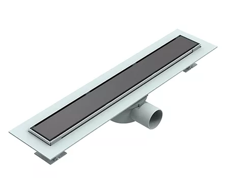
Why Do Shower Pan Bases Flex and Pool Water? Polymer Mechanics Explained
Reference Standard: CSA B45.5 / IAPMO Z124 (Plastic Plumbing Fixtures)
Short Answer
Bending Moment Fatigue Under Dynamic Point-Loading
When engineers evaluate the structural lifespan of standard sanitary fixtures, the focus often heavily relies on static weight limits. However, the reality of human ambulation within confined wet spaces introduces a much more destructive force: dynamic point-loading. As a user shifts their center of gravity during bathing, the applied kinetic force acts upon isolated zones of the acrylic or SMC (Sheet Molding Compound) substrate, generating severe localized bending moments.
Mechanism Dissection
The underlying structural architecture of premium shower pan bases dictates their survival against kinetic forces. High-gloss acrylic surfaces inherently lack the tensile strength to resist deformation independently. They rely entirely on a sub-layer composite, typically formed from multi-axis robotically sprayed fiberglass resins and a rigid skeletal framework. If the fiberglass deposition is inconsistent, or if the underlying polyurethane (PU) honeycomb support matrix contains volumetric blind spots, the applied point-load is not distributed evenly across the floor. This localized pressure induces flexural strain, forcing the acrylic matrix to undergo repeated elastic-to-plastic transitions. Over thousands of cycles, this concentrated bending moment generates severe fatigue creep, eventually surpassing the material’s yield strength and compromising the structural rigidity of the entire platform.
Extreme Pressure Timeline Model
To quantify this structural degradation, we must simulate a rigorous 1,500-cycle kinetic fatigue model applying a dynamic 300 lb load to the most vulnerable coordinates of the pan.
* Initial Flexural Phase (0-300 Cycles): The fiberglass matrix handles the kinetic energy transfer adequately. The acrylic surface exhibits microscopic elastic deflection under direct heel impact but immediately recovers its geometric baseline once the load is removed. No permanent structural changes are detectable.
* Matrix Fatigue and Delamination (300-900 Cycles): The continuous cyclic stress begins to attack the adhesive bond between the acrylic shell and the fiberglass reinforcement layer. Micro-delamination occurs at the flex nodes. The floor begins to exhibit a noticeable “spongy” tactile feedback, and the internal honeycomb cells start to micro-fracture under the repeated bending moments.
* Critical Plastic Yield (900+ Cycles): The structural matrix completely exhausts its fatigue limit. The material undergoes permanent plastic deformation, resulting in macroscopic localized depressions. These sunken zones actively disrupt the factory-calibrated drainage slopes, creating permanent pooling sectors that invite severe microbiological colonization.
Cross-System Cascading Vulnerabilities
When dynamic point-loading compromises the base structure, the destructive kinetic energy is immediately transferred horizontally toward the peripheral installations. As the center of the pan flexes downward, it exerts tremendous shear strain on the rigid drain assembly. This constant vertical oscillation acts as a mechanical lever, systematically fracturing the watertight elastomeric gaskets connecting the drain to the subfloor plumbing, inevitably resulting in catastrophic, undetectable moisture intrusion into the architectural framing.
KEY TAKEAWAYS
- Acoustic Resonance Shifts: A distinct creaking or hollow popping sound during weight transfer indicates severe sub-layer fiberglass delamination.
- Tactile Substrate Sponginess: A localized yielding sensation under the heel signifies the collapse of the underlying polyurethane honeycomb support matrix.
- Asymmetric Fluid Retention: Micro-puddles forming outside the direct drainage radius confirm that permanent plastic deformation has overridden the pre-engineered vector slope.
Hydrolysis Scission via Surfactant Permeation
Beyond physical stress, the surface chemistry of shower pan bases endures a relentless, invisible assault. The daily exposure to hot water mixed with heavy chemical detergents creates an aggressive hydrothermal environment that actively attacks the molecular integrity of the fixture’s protective gel coat.
Mechanism Dissection
Standard sanitary environments are rich in weak alkaline soaps and synthetic surfactants. These chemical agents are specifically engineered to lower the surface tension of water. While effective for cleaning, this reduced surface tension allows the heated, chemically infused moisture to penetrate the microscopic, naturally occurring pores of the acrylic gel coat. When subjected to recurrent thermal shock—the rapid alternation between ambient room temperature and 45°C hot water—the polymer chains within the acrylic matrix experience intense thermomechanical stress. This combination of chemical infiltration and thermal expansion triggers hydrolysis scission. The long-chain macromolecules of the resin are cleaved, breaking down the cross-linked structural bonds. This chemical degradation manifests initially as an irreversible loss of gloss and severe chromatic yellowing, deeply compromising the material’s structural density.
Extreme Pressure Timeline Model
Subjecting the polymer composite to a 1,000-cycle accelerated thermal shock and alkaline immersion test reveals the exact degradation trajectory.
* Surfactant Saturation Phase (0-200 Cycles): The alkaline moisture lowers the interface energy, allowing water molecules to embed deeply into the gel coat. The surface begins to lose its hydrophobic properties. Water droplets no longer bead up, but rather sheet across the surface, indicating the preliminary breakdown of the protective finishing layer.
* Molecular Cleavage Phase (200-700 Cycles): The repeated thermal expansion and contraction physically force the embedded water molecules deeper into the polymer lattice. Hydrolysis scission actively severs the macromolecular bonds. The surface develops microscopic crazing—a network of invisible fissures—and the material’s Shore hardness drops significantly.
* Structural Rupture and Friction Loss (700+ Cycles): The micro-crazing coalesces into visible hairline cracks. The chemical degradation entirely erodes the DIN 51097 certified anti-slip texturing. The floor becomes critically slick, posing a severe kinetic hazard, while the exposed deep fractures provide an ideal anaerobic environment for black mold proliferation.
Cross-System Cascading Vulnerabilities
The destruction of the surface gel coat via hydrolysis scission unleashes secondary biological hazards into the residential environment. As the polymer degrades, the resulting microscopic ravines become impenetrable to standard cleaning implements. Organic cellular material and lipid-rich residues become permanently anchored in these fissures, releasing volatile organic compounds (VOCs) and generating persistent, unmanageable malodors that permeate the entire ventilation network.

Fluid Dynamics & CNC Vector Topology
To eliminate pooling and ensure rapid fluid evacuation, manufacturing protocols must transcend basic mold-making. Relying on gravity alone is insufficient; engineers must actively manage fluid viscous drag and surface tension anomalies through extreme geometric calibration.
Execution Protocol: CNC Milled Drainage Topologies
Factories must abandon traditional manual mold shaping in favor of 5-axis CNC high-precision milling. This technology calibrates the exact drainage vector flow lines across the entire surface area. The pre-engineered pitch must be strictly locked between a 1% to 2% gradient, compensating precisely for the inherent shrinkage rates of cooling thermosetting resins. In addition, the perimeter must feature an integrated tile flange designed to mechanically absorb the Coefficient of Thermal Expansion (CTE) mismatch between the acrylic base and rigid ceramic wall tiles.
Material Expected Evolution:
By deploying CNC vector topologies, the surface effectively overcomes fluid viscous drag. The precise geometric pitch forces the water’s kinetic energy to override its own surface tension, ensuring a rapid, uninterrupted flow toward the drain aperture. The integrated tile flange acts as a dynamic expansion joint, neutralizing thermal shear stress and preventing the perimeter silicone seals from rupturing during extreme temperature shifts.
Hidden Costs and Side Effect Mitigation:
Implementing 5-axis CNC machining exponentially increases the capital expenditure for tooling. Minor vibrations in the milling apparatus can leave microscopic ridges that ironically trap water. Facilities must utilize post-machining laser-optic surface scanning to verify that the gradient is mathematically flawless before moving to the mass-production thermoforming phase.
| Structural Variable | Baseline Industry Tolerance | Advanced CNC Precision | Critical Testing Benchmark |
|---|---|---|---|
| Drainage Pitch Angle | 0.5% – 1.0% | 1.5% – 2.0% | 10-Second Complete Fluid Evacuation |
| Mold Shrinkage Rate | 3% Variance | < 0.5% Deviation | 3D Laser Scanning Verification |
| Flange Shear Stress | Rigid 90° Joint | Dynamic CTE Flange | 1,000 Thermal Shock Cycles |
| Surface Shore Hardness | 40-50 Barcol | > 65 Barcol | Scratch Resistance Testing |
| Anti-Slip Friction | Standard Texture | DIN 51097 B/C Grade | Wet Pendulum Slip Test |
PRO-TIP / CHECKLIST
- Audit the Support Matrix: Prior to installation, invert the base and ensure it utilizes a high-density PU honeycomb structure rather than sparse, randomly placed fiberglass pillars.
- Verify Thermal Expansion Gaps: Ensure the installer leaves a mandatory 3mm to 5mm expansion gap around the perimeter to accommodate CTE mismatches without buckling the pan.
- Inspect the Tile Flange: Select models equipped with a factory-integrated, raised tile flange to provide a foolproof mechanical barrier against wall-cavity moisture intrusion.
- Conduct a Pre-Install Flow Test: Pour 1 liter of water onto the furthest corner of the dry pan; verify that complete evacuation occurs rapidly without leaving residual micro-puddles.
- Check for Nano-Fortification: Request technical documentation confirming the gel coat incorporates nano-antioxidant modifiers to resist hydrolysis scission and yellowing.
- Evaluate Elastomeric Drain Seals: Ensure the drain coupling utilizes variable-durometer silicone gaskets to absorb dynamic point-loading vibrations without fracturing.
Frequently Asked Questions (FAQ)
how to silicone a shower tray
Applying sealant requires understanding thermal hysteresis. You must utilize a high-modulus, neutral-cure sanitary silicone engineered to stretch up to 25%. This elasticity accommodates the severe Coefficient of Thermal Expansion (CTE) mismatch between the shifting acrylic tray and the rigid ceramic wall, preventing catastrophic shear tears during hot water cycles.
how to hook up a shower drain
Connecting the waste assembly demands precise torque management to avoid inducing stress micro-fractures in the acrylic basin. Utilize a specialized friction gasket and plumber’s putty to create an initial seal, ensuring the locking nut is tightened evenly. Never use rigid anaerobic adhesives, which cannot absorb the kinetic vibrations generated during daily use.
how to unclog a slow shower drain
Eradicating blockages requires avoiding highly exothermic chemical drain cleaners, as the intense thermal reaction can trigger hydrolysis scission and melt the adjacent acrylic drainage aperture. Utilize specialized enzymatic lipid-degraders or a mechanical kinetic auger to safely extract coagulated keratin and cellulose particulates without damaging the synthetic pipe infrastructure.